Wattmetric Determination of Direction
We have known the principle of evaluating the total zero current IE and zero sequence voltage UNE in the 50 Hz range taking into account the intermediate angle since the first electromechanical protective circuits. The capacitive charging capacity QEcap was still determined and evaluated as a starting criterion depending on the type of device. The provision of the zero current by a harmonised Holmgren transformer group or a cable transformer is mostly necessary in the isolated grid with a ground fault current of 80...150...(300) A and in the compensated grid.
Determining measurements in an optimized way for sine and cosine circuit (wattmetric version) by calculating P0 and Q0 in the frequency range
Different known wattmetric processes estimate the reactive current IB directly from the ground current I0 and the effective current IW from the vector observations. SAVE technology specifies the effective and reactive proportions of the ground current from the Q0 and P0 circuits in the frequency area up to 1000 Hz. This has led to initial increased stability in recording the ground fault.
Recognizing intermittent ground faults in isolated and compensated grids
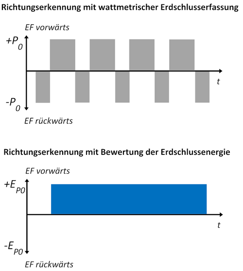
The ground fault current can be so small in compensated grids that the error arc instantly switches off again. The phase voltage of the faulty phase then recurs and, once this exceeds a critical value, it is reignited. This process repeats itself as long as the error location is on the grid and the error has not yet been fixed. This process is identified as an intermittent ground error. The problem is that, at the time of the reignition, a discharge current is flowing into the two healthy phases. This impulse current flows in the opposite direction, such as the zero sequence voltage UNE. As a result of both the effective current IWE (PE) and reactive current ICE (QE) always changing the sign, a protection for the ground fault direction likewise always changes the recognition of the direction without suppressing the intermittent ground errors. Although it appears as if the current is flowing in the wrong direction of the fault during the ignition process (discharge process of the affected phase), a medium amount of power flowing in the operative direction is noticed after a while (window/energy). The direction can therefore be recognized by the zero system energy E0 sign used. This also gives the plausibility that the discharge is driven through a phase and the following charge reversals have driven the two healthy phases.